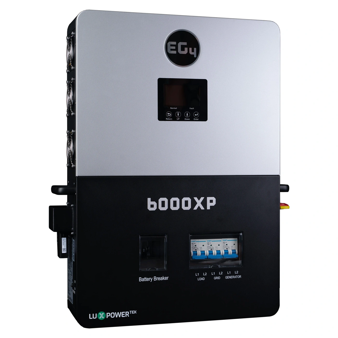
One EG4 6000XP can be a very capable center for an off-grid system. It provides 120/240-volt split-phase power, accepts solar through two maximum power point tracking (MPPT) inputs, and has a nominal 6,000-watt alternating-current (AC) output. But some Hawaii homes, workshops, and small businesses eventually need more output than one inverter can provide.
That is where I like the 6000XP’s ability to work in a coordinated parallel system. Two units provide a nominal 12,000 watts of inverter output, and three provide 18,000 watts. EG4 documents parallel operation for up to 16 units. You do not need to start with the maximum. In many cases, the practical choice is to build around the loads you have now and leave room for a planned expansion.
Start with the loads, not the inverter count
Suppose your home has a well pump, refrigerator, freezer, pressure pump, and several air-conditioning or workshop loads. The question is not simply, “How many kilowatts do I want?” I want to know which loads run together, which motors start together, and which circuits truly need to operate during an outage.
A second 6000XP can give the system more continuous output and more ability to handle simultaneous loads. It does not automatically make every existing circuit appropriate for backup. The service-panel arrangement, load balancing, motor-starting behavior, and battery capability still have to be evaluated as one system.
The battery has to grow with the inverter
This is the part customers sometimes miss. Adding another inverter adds available output, but it also increases possible battery-side demand.
As a simple nominal estimate, 12,000 watts divided by a nominal 48 volts is about 250 amps before inverter losses. At full output, the battery current will be higher after losses, while the permitted current may be lower because of the battery model, battery-management-system (BMS) limits, communication settings, temperature, wiring, and manufacturer instructions. That 250-amp figure is a planning example, not a final battery or conductor rating.
EG4 lists a maximum discharge current of 140 amps per 6000XP and recommends more than 200 amp-hours of battery capacity per inverter. That gives us a useful starting point, not a complete battery design. For two units, I would not assume that one small battery is enough simply because the inverter screens can be connected together. The battery bank needs enough energy and discharge capability for the loads you expect.
This is where the exact battery model matters more than a general promise that “48-volt batteries work.” I start with a battery model and communication path that EG4 documents as compatible. When closed-loop communication is supported and configured, the battery-management system can provide charging and discharge limits to the inverter instead of leaving every limit to manual guesswork.
Parallel operation is a coordinated system
The 6000XP’s parallel setting identifies whether the system is using no parallel operation, single-phase parallel operation, or three-phase parallel operation. It also assigns the phase role and includes the Battery Share function.
In ordinary language, the units need to agree about who they are, what phase arrangement they belong to, and how they should share the work. That is why I treat parallel communication as part of the system design, not as an accessory added after the power wiring is finished.
The inverters use dedicated parallel communication connections, DIP-switch roles, and phase settings. The battery has its own communication path. Depending on the battery, that path may use Controller Area Network (CAN) or RS-485, a wired serial communication standard. The exact cable, protocol, battery selection, and firmware path must match the equipment involved.
A sensible expansion sequence
For a growing Hawaii system, I like a staged plan. First, document the loads and decide which circuits belong on backup. Next, select the battery bank that can support the intended inverter output. Then confirm that the number of 6000XP units, phase arrangement, battery communication, monitoring path, and photovoltaic input plan are compatible.
After installation, commissioning should prove the system in steps. The installer can confirm the battery voltage and communication, verify each inverter’s identity and phase role, check the parallel status, bring solar input online, and add loads gradually. One useful detail is that each inverter’s display shows that inverter’s contribution, not necessarily the total system contribution. A staged check makes it easier to see whether a problem belongs to the battery, one inverter, the communication network, or the load panel.
For a general lesson, Pacific Yacht Systems’ How To: Marine Electrical Seminar - Inverter/Charger - Episode 4 of 12 explains how inverter wattage relates to simultaneous loads, why installers may stack multiple inverters for larger loads, and why the battery bank and installation details matter as the system grows. It is not a 6000XP setup lesson, but it gives you a useful way to think about the same design decisions.
Where I see the 6000XP fitting
I see the EG4 6000XP fitting especially well when you want an off-grid system that can start at a manageable size and grow around real loads. One unit may suit a smaller home, cabin, workshop, or essential-load panel. Two or more can make sense when the home has larger simultaneous loads, more demanding motor equipment, or a future expansion plan.
The important part is matching the whole system: inverter output, battery current, solar input, communication, protection, and the loads you actually intend to run. If you are considering one 6000XP now or a parallel system later, contact SolarMan. I can help you compare the starting configuration with the expansion path before equipment gets ordered.