One detail I like about the SimpliPHI 6.6 is that the battery isn’t pretending to be the whole power system. It stores energy and protects its cells, while a separate inverter handles the home’s alternating-current loads. That separation gives us useful choices. If we want closed-loop coordination, though, the battery, inverter, and any monitoring gateway need the right data path between them.
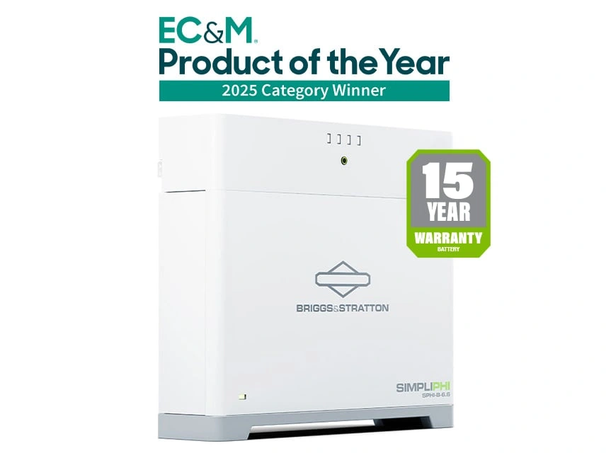
The SimpliPHI 6.6 can operate without communication. Even so, I generally want the communication plan settled before we order equipment. When a compatible battery can share its operating information with the inverter, the system has better information than it would from manually entered limits alone.
What the battery and inverter each do
Each SimpliPHI 6.6 battery is a 51.2-volt nominal lithium iron phosphate, or LFP, battery with 6.656 kilowatt-hours of rated capacity. The battery-management system monitors the cells and manages the battery’s permitted charging and discharging. The compatible inverter converts that stored direct-current energy into alternating-current power for your home. Depending on the inverter and system design, it may also manage charging from solar, the utility, a generator, or another approved source.
Those are different jobs. The inverter needs to respect the battery’s operating limits, while closed-loop communication can give the inverter more current, voltage, temperature, and status information to work with. That does not make the system automatic or self-designing, but it can make the relationship more coordinated.
Communication is more than one cable
Briggs & Stratton lists Controller Area Network, or CAN, and RS-485, a wired serial communications standard, for the SimpliPHI 6.6 platform. These are communication methods, not interchangeable labels for any cable that happens to fit. The exact inverter, battery controller, gateway, cable, and firmware path all matter.
On a supported installation, the battery modules connect through the RapidStak system to the SimpliPHI 6.6 battery controller. From there, the controller can communicate with an approved inverter or EnergyTrak monitoring equipment through the documented connection path. An EnergyTrak gateway can add battery monitoring, over-the-air firmware updates, alerts, and service visibility when it is part of the system.
That’s the practical benefit: if the inverter reports a low-battery condition or reduced charging, I want to know whether the battery is actually limiting current, whether the inverter is using the correct profile, or whether the communication path is missing. Without that information, two different problems can look very similar on a screen.
Why the inverter match comes first
“It’s a 48-volt battery” is only the beginning of an inverter match. The inverter must support the battery’s voltage range, charge and discharge capability, communication method, and approved settings. Briggs & Stratton publishes integration material for specific inverter families because the connection and commissioning process can vary from one manufacturer to another.
For example, the SimpliPHI 6.6 system specifications list a maximum continuous discharge rate of 130 amps and a maximum continuous charge rate of 100 amps per battery. Those figures help us understand the battery’s capability, but they do not automatically tell us what one inverter, one stack, or an entire home will use. The inverter, battery count, temperature, wiring, protection, and manufacturer settings still have to agree.
I also don’t want a customer to assume that adding a communication cable magically increases power. Communication improves coordination and visibility. It does not turn one battery into a larger battery or make an inverter capable of more output.
A clean commissioning conversation
Before installation, I’d want four answers:
- Which exact inverter model is being paired with the SimpliPHI 6.6?
- Does that inverter have a documented SimpliPHI integration path?
- Is the system using only inverter communication, or an EnergyTrak gateway as well?
- Who will confirm the battery profile, firmware, detected equipment, and final operating limits?
Those questions are not busywork. Briggs & Stratton’s current support materials separate battery installation, inverter integration, gateway setup, and monitoring. That gives the installer a chance to catch a missing controller, wrong cable path, unsupported inverter profile, or incomplete monitoring setup before the system becomes your everyday backup power.
If you want to see the physical idea, Solar Builder’s Click. Done? SimpliPHI 6.6 Home Battery Overview walks through the RapidStak connector, the external-inverter approach, and the role of closed-loop communication. It’s a useful product lesson, not a substitute for the integration guide for your exact inverter.
This is where I can help. Bring me the loads you want backed up and the inverter you’re considering, and I’ll look at the battery count, power requirements, communication path, monitoring equipment, and commissioning plan together. The SimpliPHI 6.6 is a strong option when those pieces are matched deliberately—not just because the battery has a convenient connector.