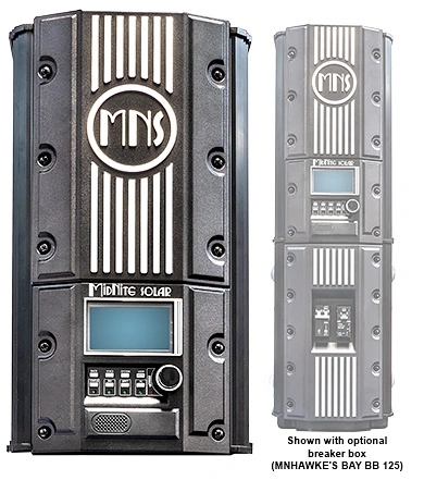
What I like about the MidNite Hawke’s Bay is that it gives us room to plan the solar side of a system properly instead of treating safety equipment as an afterthought. It is a maximum power point tracking charge controller for 48-volt battery systems, with a photovoltaic (PV) input rated up to 600 volts. It is available in 90-amp and 120-amp versions. That makes it useful for larger arrays, but higher-voltage solar also deserves a clear protection plan.
The Hawke’s Bay has a pre-installed options board that accepts separate MidNite plug-in modules for arc-fault protection, ground-fault protection, and rapid shutdown. You may not need every option on every project. The point is that the controller gives us a defined place to evaluate those functions while we are designing the array, disconnects, conductors, and battery equipment.
Three different safety jobs
These features are related, but they do not do the same job. An arc fault is an unintended electrical arc, often associated with a damaged conductor or poor connection. MidNite’s arc-fault sensor looks for the electrical noise associated with that condition.
Ground-fault protection looks for current leaving the intended PV circuit and finding another path to ground. MidNite’s Arc Fault/Ground Fault kit identifies a 0.5-amp differential between the photovoltaic conductors. When the kit detects the applicable fault, it can activate remote-trip breakers to disconnect the PV input and, where the system is designed that way, the battery-side circuit.
An arc- or ground-fault trip is not the same event as rapid shutdown. The first functions respond to detected electrical faults. Rapid shutdown responds to a separate shutdown signal and is intended to reduce photovoltaic voltage for firefighter safety when PV conductors are on or in a building. The Hawke’s Bay can accept a SunSpec-compliant rapid-shutdown transmitter module, but the complete system still depends on compatible array equipment, the shutdown initiator, the wiring method, and the requirements adopted by your local authority having jurisdiction.
Why this matters on a Hawaii roof
A high-voltage array can be a good way to move solar power from the array to the controller, especially when the distance is significant. But a string can still produce dangerous direct-current voltage whenever sunlight is present. Turning off a breaker is not the same thing as making every rooftop conductor safe, and rapid shutdown is not a substitute for correctly sized over-current protection, disconnects, grounding, or careful installation.
That is why I prefer to discuss the safety path at the same time as the string design. We look at the array voltage, the controller’s limits, the equipment location, the conductor route, the breaker arrangement, and whether the project needs arc-fault, ground-fault, or rapid-shutdown equipment. The Hawke’s Bay’s optional breaker box can help organize required over-current protection and disconnects, but MidNite identifies that box as an option rather than a universal requirement.
Where the Hawke’s Bay fits
Picture a 48-volt battery system with a high-voltage rooftop array feeding a Hawke’s Bay 90 or Hawke’s Bay 120. The controller handles the solar charging. The battery bank and inverter handle stored-energy service. The protection modules watch for specific fault conditions, while the rapid-shutdown equipment handles the separate emergency-shutdown function. Those pieces support one another, but none of them replaces the others.
That separation is useful when we are choosing equipment. A customer may need the high-voltage charging capability but not a rapid-shutdown arrangement on a ground-mounted array. Another customer may have a rooftop project where the local inspection requirements make shutdown equipment an important part of the design. I would rather match the option to the actual project than automatically sell a package that does not fit.
What I would settle before ordering
I would confirm the exact Hawke’s Bay model, the photovoltaic string voltage in hot and cold conditions, the battery manufacturer’s charging limits, and the protection method required for the site. Then I would verify that the selected arc-fault, ground-fault, rapid-shutdown, breaker, and array devices are compatible with one another and accepted by the local inspector.
For a plain-language introduction to the reason rapid shutdown exists and what it is meant to accomplish, the Sean White lesson from HeatSpring is worth watching. It explains the firefighter-safety purpose and the difference between common compliance approaches without pretending to design your particular Hawke’s Bay system.
If you are considering a Hawke’s Bay for a Hawaii home, cabin, or small commercial system, contact SolarMan with the battery voltage, approximate array size, array location, and distance to the controller. I can help you decide whether the 90-amp or 120-amp model and the available protection options make sense before the equipment is ordered.