I like the Fortress Power eBoost because it gives us a serious battery starting point without closing the door on future growth. One eBoost stores about 16 kilowatt-hours of energy, and Fortress Power designs the system for parallel expansion. But before we add another battery, I want the system to have a clear communication plan. The power cables matter, of course. The data path matters too.
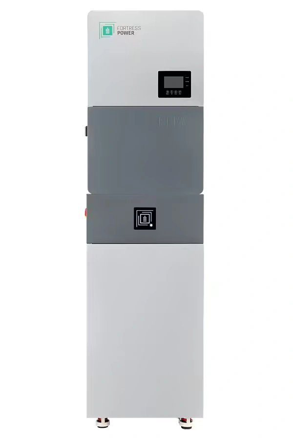
The eBoost uses closed-loop communication with compatible equipment. In plain English, the battery can share information such as its state, current limits, and operating condition with the inverter instead of leaving the inverter to guess from voltage alone. That helps the inverter make better charging and discharging decisions.
Communication is part of the battery system
You’ll see the term CAN in the Fortress documentation. It means Controller Area Network, a communication method used by many batteries, inverters, vehicles, and industrial controls. The eBoost also lists RS-485, another wired serial communication standard. You don’t need to become a communications engineer, but you do need the exact battery, inverter, cable path, and protocol to agree with one another.
That is why I don’t treat a battery communication cable as an optional accessory that we figure out after the equipment is powered. The battery-to-inverter link, the battery-to-battery link, the correct terminator arrangement, and the selected inverter protocol all belong in the system plan.
For a single eBoost, the battery communicates with the inverter through the approved system equipment. In a documented parallel bank, one battery becomes the primary battery—the one communicating with the inverter—and the other batteries join through the battery network. Fortress’s installation guidance says the other batteries should energize when the primary battery is started and the communication path is correctly connected. That gives us a useful commissioning check without treating a green light as proof that every setting is correct.
Expansion is more than adding another box
Suppose you begin with one eBoost and later decide that the battery should carry more overnight load or provide more reserve during a long outage. Adding a second unit can increase the available battery-side current and stored energy, but it does not change the battery-bank voltage. The inverter, protection equipment, conductors, communication network, and settings still have to support the larger bank.
Fortress Power’s current product page lists expansion up to 384 kilowatt-hours, or 24 eBoost units, when the latest firmware is installed. The current installation manual still describes the eBoost as scalable to 256 kilowatt-hours and up to 16 units, depending on the configuration. I treat those as revision and configuration details to reconcile—not numbers to mix casually. Before we order additional batteries, I want to confirm the current battery revision, firmware path, exact eWay and inverter arrangement, and Fortress’s supported unit count for that system.
Why firmware belongs in the conversation
Firmware is the software inside the battery and related equipment. It can affect compatibility, communication behavior, monitoring, and supported system configurations. Fortress maintains a separate eBoost firmware page with update instructions, drivers, software, and firmware files. That is a good sign for a product that is expected to grow and work with changing inverter platforms.
My recommendation is simple: don’t update equipment casually, and don’t assume the newest file belongs on every unit. The installer should identify the exact equipment and follow the current Fortress instructions. If a system is being expanded, I want all the batteries and connected controls to be considered together rather than updating one box and hoping the rest catches up.
What I want settled before startup
Before commissioning, I want to know which inverter the eBoost is paired with, whether the system is using closed-loop communication, which battery is primary, how the parallel communication path ends, and whether the current firmware supports the intended arrangement. For an Envy inverter, Fortress’s current Quick Start Guide identifies Lithium 18 as the recommended closed-loop protocol. Other inverter families use their own settings, which is exactly why I want the inverter model and documentation settled first.
Fortress also provides commissioning guidance through its Pro App for eBoost and Envy systems, including Guardian setup, system registration, and configuration.
A general CAN lesson can help explain why this matters. Kvaser’s training video shows how a Controller Area Network uses a defined communication path, differential signaling, and proper network termination to let devices exchange reliable information. It is not an eBoost setup video, but it gives you a useful picture of why “the batteries are connected” and “the batteries are communicating correctly” are two different statements.
If you’re considering one eBoost now with the possibility of adding more later, contact SolarMan before choosing the battery count. I can help match the eBoost bank to the inverter, loads, communication equipment, firmware plan, and the kind of backup you actually want. That conversation is easier before installation day than after a second battery is sitting in the driveway.