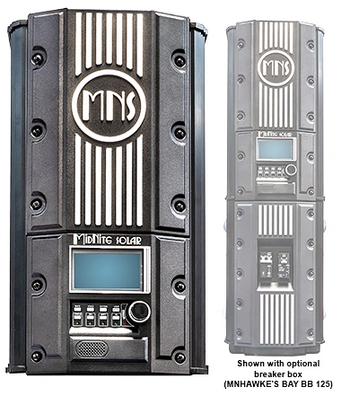
The Hawke’s Bay is the kind of charge controller I want planned before anybody starts flipping breakers. It can take a high-voltage solar array and turn that energy into useful charging current for a 48-volt battery bank, but the order of the first startup matters.
I would begin on the battery side. The Hawke’s Bay is a 48-volt controller, and MidNite’s manual identifies 29 to 65 volts DC as a good battery-voltage range for the startup check. Once the battery bank is present, the controller has the reference it needs to power up and show you what it is doing.
Battery settings come before solar power
After the battery connection is confirmed, I’d program the charge settings to match the battery manufacturer’s instructions. That means chemistry, absorb voltage, float voltage, charge limits, and any other settings that apply to that particular battery bank.
This is especially important with lithium batteries. The Hawke’s Bay can charge lithium, flooded lead-acid, AGM, and other battery types, but that does not mean one generic profile is right for every bank. Your battery’s documentation still controls the settings. A charge controller is powerful equipment; it should not be guessing what your battery needs.
MidNite describes the charging process in stages. Bulk sends as much available current as the controller can provide until the battery reaches the absorb-voltage setting. Absorb holds that voltage while the charging current tapers. Float then maintains the battery at its float setting. Seeing those stages on the display gives you a much better picture than simply asking whether the panels are “on.”
Then we check whether the array fits
The Hawke’s Bay is not a conventional low-voltage solar controller. MidNite lists a 600-volt maximum PV operating voltage, a 220-volt minimum open-circuit-voltage specification, and an MPPT window of 185 to 585 volts in the current Hawke’s Bay 120 documentation.
There is one useful distinction during commissioning. The manual says 240 volts or higher of open-circuit voltage is good for the MPPT check. I would use the exact controller documentation and the panel datasheet together rather than treating every number as interchangeable.
Open-circuit voltage, or Voc, is the voltage measured when the array is not delivering operating current. Maximum-power voltage, or Vmp, is the working voltage while the array is producing power. Both numbers matter, and cold weather can raise Voc.
For a Hawaii system, the cold-weather increase may be smaller than it would be in a mainland winter, but it still belongs in the design calculation. I want the string’s temperature-corrected Voc below the Hawke’s Bay’s 600-volt ceiling. I also want the operating voltage to land inside the MPPT range rather than barely reaching the minimum on a hot, bright afternoon.
A simple example makes the sequence easier to understand
Imagine a 48-volt battery bank and a PV string designed to operate around 400 volts. The startup conversation is not “connect everything and see what happens.” First, the controller sees the battery and receives the correct battery settings. Then a qualified installer checks the array’s open-circuit voltage against the design values while the PV input remains disabled.
Once that check passes, the PV input can be enabled and the operating voltage and charging behavior can be observed. I would look for a sensible relationship between PV voltage, battery voltage, charging stage, and output current.
A sunny array can still show little charging current when the battery is already near full, another charging source is holding the battery voltage up, or the controller is in a resting condition. That is normal behavior—not automatically a failed controller.
The high-voltage side changes the equipment around it
A 600-volt PV input also means the disconnects, overcurrent protection, combiner equipment, wiring methods, and enclosures have to be rated for the actual array voltage. The optional Hawke’s Bay breaker box organizes the battery and PV protection and disconnect functions, but the manual identifies it as optional rather than required for every installation.
Type 1 does not mean outdoor-rated. MidNite’s manual calls for indoor or compartment installation, protection from rain and moisture, and placement out of direct sunlight. I would keep the controller vertical, accessible, and away from gases produced by the batteries. Those details matter in Hawaii’s warm, damp conditions because they affect long-term serviceability.
This is where the Hawke’s Bay earns its place
I like the Hawke’s Bay when a 48-volt battery system needs a serious amount of solar charging and the array layout benefits from higher PV voltage. Its display, charge-stage information, adjustable output limits, battery-temperature input, and MidNite communication features give us useful information during startup and later service.
Martin Lorton’s general solar-power lesson is helpful background before our design conversation because it walks through how solar panels, a charge controller, a battery bank, and an inverter relate in an off-grid system. It gives you the system picture first, so the Hawke’s Bay’s battery-side and PV-side checks make more sense. It is not a Hawke’s Bay setup lesson.
If you are considering a Hawke’s Bay for a Hawaii backup or off-grid system, bring me the battery model, the panel datasheet, the planned string layout, and the distance between the array and equipment. I can help match the controller, protection, battery settings, and startup plan before the first breaker is closed.