A larger Pytes V16 bank can give a Hawaii home much more breathing room after sunset. One V16 is rated at 16 kWh. Three batteries provide 48 kWh of nameplate storage, while eight provide 128 kWh. That arithmetic is useful, but the batteries still need to operate as one planned system rather than as separate boxes joined wherever the cables happen to reach.
That is where I like the V16’s expansion path. Pytes documents up to 16 V16 units in parallel, or up to 256 kWh of nameplate storage, without a separate Pytes hub. The V16 is also designed for outdoor use, with an IP66 enclosure and wall- or ground-mount options. For a larger property, farm, or off-grid home, that combination gives us a practical way to grow the battery bank without changing battery families halfway through the project.
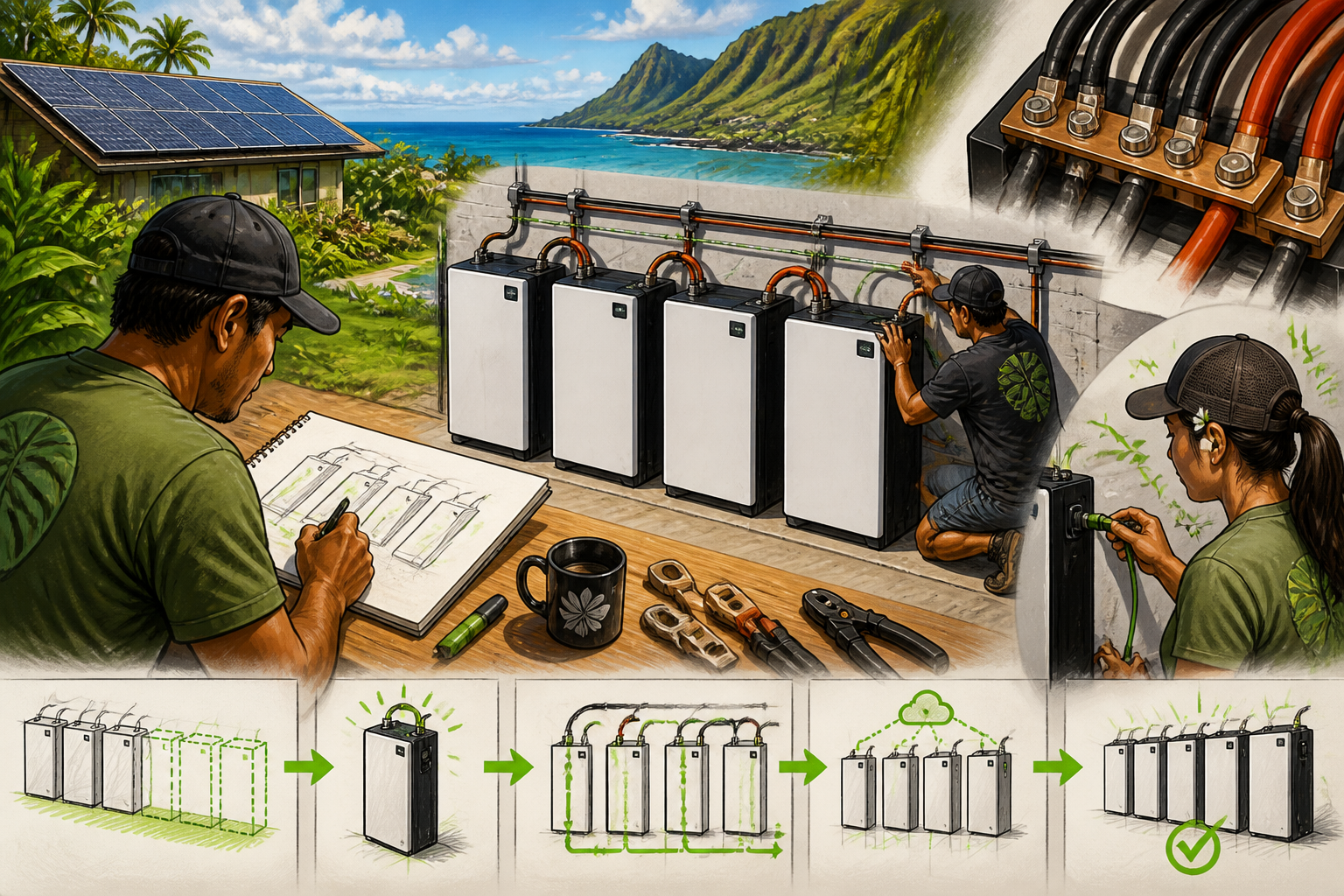
Parallel adds storage, not unlimited inverter power
Connecting V16 batteries in parallel keeps the bank at the same nominal voltage while increasing its total energy capacity. It can also give the system more battery-side current capability, but that does not mean the inverter will automatically deliver more power. The inverter, battery-management system, protection equipment, cable size, busbars, and operating temperature all remain part of the limit.
Pytes lists 51.2 volts nominal and 16 kWh for each V16. Its current datasheet also distinguishes recommended charge and discharge currents from the higher maximum continuous current. I don’t use the largest number as a promise to the homeowner. I match the inverter and load plan to the applicable battery limits, then confirm that the complete bank can share the expected current without making one battery do more work than the others.
Give every battery a fair path to the busbars
For a larger bank, I want the positive and negative connections organized through properly rated busbars or the applicable Pytes combiner equipment. Pytes’ V16 documentation shows each battery connecting to positive and negative busbars, with the busbars then feeding the inverter. That arrangement is much easier to inspect and expand than letting the inverter feed one battery while the remaining batteries hang off a chain of jumpers.
Current follows the path of least resistance. If one battery has much shorter, larger, or cleaner cable paths than another, it may take more of the charge and discharge work. I therefore plan the battery-to-busbar paths as evenly as practical, using matching cable sizes and equal or closely matched lengths where the layout allows. The final conductor, fuse, breaker, busbar rating, and torque details belong to the equipment manuals and the qualified installer—not to a conceptual drawing on a webpage.
If you want to see that current-sharing idea in a simple visual, EXPLORIST.life’s battery-bank lesson walks through parallel wiring, busbar connections, and the differences between parallel, series, and series-parallel arrangements. It uses general battery examples rather than the V16, but the planning principle is the same: a growing battery bank needs an organized path to the inverter.
The communication network needs one clear leader
A parallel bank also has a communication structure. Pytes describes one V16 as the master and the remaining batteries as slaves connected in cascade. The master communicates with the inverter through the documented CAN or RS485 path, depending on the inverter and approved communication method. The exact cable pinout and inverter profile matter; a cable that physically fits is not automatically the right cable.
I want the master battery identified before startup, the inter-battery communication cables installed in the correct order, and the inverter’s battery protocol selected for the exact model. If the batteries cannot share their status with one another—or the inverter cannot correctly read the master—the system may charge or discharge with the wrong information. That is not a small setup detail. It changes how the system protects the batteries.
Commission the bank in stages
My preferred sequence is calm and deliberate. First, confirm that the batteries are the same model and intended configuration, that the power paths and communication paths are complete, and that the inverter settings match the approved battery relationship. Then verify battery voltage and polarity before energizing the power electronics.
Pytes’ startup guidance says the V16 battery should be powered before the inverter. In a parallel arrangement, the master battery’s switch is used to power the system. After the battery indicators show normal operation, the inverter can be started and its battery status checked. I want to see agreement between the battery bank, inverter, and monitoring system before placing heavy household loads on the system.
That staged approach also makes future expansion easier. If you later add another V16, we need to confirm that the new unit, firmware or communication arrangement, state of charge, power cables, busbars, and inverter settings all belong in the same bank. Expansion is not simply a matter of bolting on another 16 kWh.
Where a larger V16 bank fits
This approach makes sense when your loads, outage expectations, or off-grid plans are already pushing beyond one battery. It can fit a whole-home backup system, a remote Hawaii property, or a site where future loads may grow. It may not make sense to build a 256 kWh bank just because the product can support it. I start with your overnight loads, surge-producing equipment, solar production, inverter capacity, and the reserve you actually want.
Pytes’ installation guide is useful because it shows the equipment relationship, but the final design still needs to be matched to your inverter and site. If you’re considering two or more V16 batteries, contact SolarMan. I can help you work through the battery count, busbar layout, communication plan, inverter match, and a commissioning sequence that leaves you with a bank you can understand and expand responsibly.