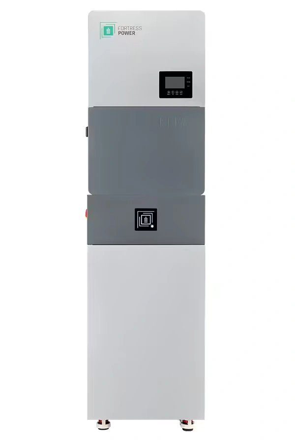
When we choose the number of Fortress Power eBoost batteries, I don’t want us to look only at the 16 kilowatt-hours (kWh) on the nameplate. The inverter matters just as much. A battery bank can have plenty of stored energy and still be the wrong size if the inverter asks for more battery-side current than the bank is meant to provide.
That is why I start with two questions: how much power do you want to run at once, and how hard will the inverter charge or discharge the battery? The eBoost gives us a strong starting point because each unit is a 51.2-volt lithium iron phosphate battery. Fortress lists 16.077 kWh of nominal energy per unit, but energy and power are different jobs.
One eBoost fits naturally with a 6.5-kilowatt inverter
Here’s a simple example. A 6,500-watt inverter divided by the eBoost’s 51.2-volt nominal battery voltage is about 127 amps:
6,500 watts ÷ 51.2 volts ≈ 127 amps
That is a nominal battery-side estimate before inverter losses. The real current can be higher when the battery voltage is lower, when the inverter is working hard, or when a motor load starts. Even so, the calculation shows why one eBoost is a sensible starting point for a Fortress Power Solo 6.5K system when the rest of the design fits.
Fortress Power’s compatibility guidance lists one eBoost as the minimum recommended battery count for the Solo 6.5K. That does not mean every home will get the same runtime. It means the battery count and inverter relationship have a documented starting point. Your overnight energy use, well pump, refrigerator, air conditioning, and other loads still decide how much storage you actually want.
A 12-kilowatt inverter deserves a closer look
Now consider a Fortress Power Envy 12kW inverter. The same quick estimate becomes:
12,000 watts ÷ 51.2 volts ≈ 234 amps
That number is close to the eBoost’s documented 250-amp closed-loop discharge limit per unit. Closed-loop means the battery and inverter exchange operating information, including limits, instead of the inverter relying only on manually entered settings.
At 234 amps before losses, there isn’t much room left for lower battery voltage, temperature-related limits, or a demanding starting event. Fortress still lists one eBoost as the minimum recommended count for the Envy 12kW, but that minimum is not a promise that one battery will comfortably support every 12-kilowatt load profile.
Two eBoost units can provide more battery-side current and more stored energy at the same time. That may be the better choice when you want whole-home backup, large motor loads, longer operation after sunset, or room to grow. It is not an automatic requirement for every Envy 12kW installation; the actual loads, inverter limits, communication setup, and approved system configuration still matter.
Charging current is a separate check
Discharge is only half the conversation. Fortress lists 180 amps of closed-loop charge current and 250 amps of closed-loop discharge current for each eBoost. Those are operating figures for a communicating system, not interchangeable numbers.
The installation manual adds another boundary: do not install an inverter with charging capacity greater than 250 amps per eBoost, even if someone intends to limit the inverter manually or digitally. In other words, we compare the inverter’s maximum charger capability with the battery-bank count first. Then we confirm the closed-loop settings, communication protocol, and actual system design.
Communication has to be part of the design
The eBoost communicates through the product’s supported battery and parallel-system communication paths. A communication cable by itself does not prove that the battery and inverter are exchanging the right information. The exact inverter protocol, firmware, battery count, and commissioning process have to agree.
For that part of the lesson, Kvaser’s CAN Basics Training Introduction is a useful general companion. It explains how a Controller Area Network (CAN) carries information between devices and why the physical connection, message format, and higher-level protocol are separate pieces. That is the same reason I don’t treat any cable as proof that an eBoost and inverter are operating in closed loop. The exact battery protocol still has to match the inverter.
Choose the bank around the home you actually run
I like the eBoost when a customer wants a real battery platform rather than a small add-on battery that forces every future decision around today’s loads. One unit gives you a useful starting point. Two or more can support more energy, more battery-side current, and a larger expansion plan.
The current Fortress Power product information lists expansion up to 24 eBoost units with the latest firmware. Fortress also distinguishes the eWay, intended for multi-battery and whole-home systems, from the eWay Lite, intended for a single or secondary battery. If you expect the bank to grow, that choice belongs in the first design conversation, not after the equipment is already mounted.
If you’re considering an eBoost 16kWh LFP Battery, contact SolarMan before choosing the battery count. Bring me your inverter choice, the largest loads you want to run together, and the amount of overnight energy you want available. I’ll help match the battery bank to the actual system instead of sizing it from one number on the label.