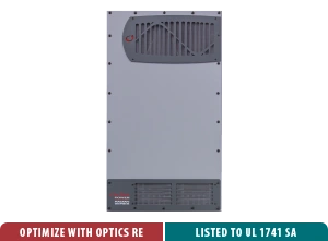
If an OutBack Radian system stops working, I don't automatically assume the answer is a brand-new inverter. On compatible models, the problem may be repairable at the module level. That can matter a lot in Hawaii, where the batteries, wiring, load center, generator controls, and other inverters may already be doing exactly what you need.
OutBack's Radian service documentation identifies replaceable assemblies called the PCBA Module and Power Module. The PCBA Module includes the power-supply, control, voltage/current-sense, and AC boards, along with connections for the AC wiring, MATE3 system display, auxiliary functions, remote temperature sensor, and Power Module. The Power Module contains the transformer, FET board, and related power components. In plain language, a qualified technician may be able to replace the part of the inverter that failed instead of removing the entire system.
The first decision is identifying the failed section
A Radian that will not start, will not communicate, or shows an unusual power-conversion problem can have more than one possible cause. A control-board problem and a power-module problem are not interchangeable repairs. OutBack's service instructions specifically say to identify which power module needs replacement before proceeding, and they list different assemblies for different Radian models.
That is why I want the exact label from the inverter before I recommend a repair path. GS8048A and GS4048A are not just numbers on a sales sheet. The model affects the internal connections, firmware behavior, configuration, and the replacement parts that apply. A nearby model or a used board that merely looks similar is not a safe substitute.
Save the system before changing the hardware
One of the best things about an OutBack installation is that its settings can be part of the repair plan. Before a board replacement, the service instructions call for saving the inverter configuration to an SD card and recording the firmware revision and stacking settings. That gives the technician a way to restore the system's previous operating plan instead of rebuilding every setting from memory.
This becomes even more important when several Radian units work together. If a PCBA Module is replaced in a stacked system, the repaired inverter's firmware needs to match the other Radian units, and the stacking arrangement needs to be confirmed again. If the repaired unit was the master, the configuration deserves especially careful attention because it coordinates the rest of the system.
Repair can preserve the parts that already fit your home
Suppose you have a GS8048A system connected to a 48-volt battery bank, a GS Load Center, a MATE3s display, charge controllers, and a generator. A board-level repair may allow those surrounding components to remain in place. You are still dealing with a serious electrical repair, but you may not need to redesign the battery bank, change the AC distribution, move communications cables, or replace equipment that was not actually damaged.
That is the practical value I see in supporting legacy OutBack equipment. The system relationship matters more than the inverter by itself. A repair is worthwhile when the existing architecture is sound, the replacement assembly is correct, and the final settings and safety checks can be documented.
This is qualified service, not a casual DIY project
The Radian service documents require all AC and DC sources to be disconnected and verified de-energized before internal work. They also warn that stored electrical energy can remain inside the inverter and that sensitive boards can be damaged by static electricity. This is work for a qualified technician with the proper meter, procedures, replacement part, and model information.
After the repair, the system is not finished just because the inverter turns on. If the PCBA Module was replaced, the technician should apply the applicable firmware steps, restore or re-enter the configuration, verify the model and stacking roles, and check the AC input and output. If only a Power Module was replaced, OutBack's service instructions treat the power-up process differently and say to ignore the firmware-update and configuration-file steps for that repair. In either case, generator-start functions, bypass operation, and other enabled features should be tested before the system is handed back to you.
OutBack's own support library includes a short lesson on replacing a Radian power-supply board. I like it because it shows that these systems were designed with serviceable assemblies in mind, while also making clear that internal repair involves real electrical hazards. It is a general service lesson, not a substitute for the exact manual and the exact model on your wall.
If your OutBack Radian, FXR, or VFXR system is showing a fault, or its MATE or HUB communications are involved, contact SolarMan before assuming the whole installation needs to be replaced. Send me the model numbers, the symptoms, and what the MATE display is reporting. I can help determine whether a repair, a board replacement, or a broader system upgrade makes the most sense.